Characteristics and Applications of Heavy Oil Burners
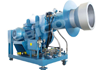
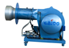
The heavy oil burner is a combustion device designed specifically for heavy oil with high viscosity and poor atomization performance, used to improve the combustion performance of heavy oil. It mainly consists of a heavy oil tank, diesel tank, oil filter, heavy oil supply pump, heat exchanger, and light and heavy oil switching valve. Fuel pump, pressure regulating valve, burner and its delivery pipeline, etc
Equipment principle: Heavy oil enters the burner in two ways: vortex oil and axial flow oil, similar to the internal and external air of the burner. The vortex oil is distributed in a circular shape externally; Axial flow oil is a straight cylindrical jet in the middle. When it reaches the head of the spray gun, it will gather into a path and enter the kiln through the nozzle hole of the atomizing plate. The atomization plate is divided into various specifications based on the size of the nozzle hole. During the heating and feeding process, replace atomizers of different specifications as needed. The structure of the kiln end burner is the same as that of the kiln head, but the proportion of internal air is much greater than that of external air. The difference between the oil inlet pipe and the kiln head burner is that one method is used for oil inlet and the other method is used for oil return.
Burner technical features:
1. Flame stabilizer is used to maintain a stable vortex circulation at the root of the flame, reduce the rotation of internal air, and reduce the primary air volume by half.
2. Use a flame-retardant cover to prevent the arbitrary dispersion of heavy oil carried in the airflow, resulting in braking effects. The flame shape has a reasonable history, avoiding high temperatures at the kiln head and extending the service life of the kiln head protective iron.
3. The external clean air has an intermittent rectangular direct jet, which reaches the front of the burner and becomes an annular gap jet. At the same time, increase the area of the annular gap to extend the flame and increase the average temperature inside the kiln.
4. The vortex blades are installed at the front end of the inner air duct, 2cm away from the front end of the outer air duct wall, to gather flames and avoid high temperatures at the kiln head. The first handle of the burner can be adjusted. When leaving the factory, the position of the rotating blade is located at the 6 "position of the scale. The adjustment range is 0} 6cm. There is no negative value. The internal wind vortex can only be pulled back to extend the flame.
5. The central wind blows back the high-temperature gas around the nozzle, not only cooling the inside of the nozzle, but also cooling the end face, thereby protecting the burner head and extending the burner's service life.